Thursday, 16 March 2017
Thursday, 2 March 2017
Thursday, 30 July 2015
Electric Circuit
The Electric Circuit:-
A basic electric circuit is an arrangement of physical components that use voltage, current and resistance to perform some useful function.
Direction of Current:-
–Two conventions for the direction of electric current.
A basic electric circuit is an arrangement of physical components that use voltage, current and resistance to perform some useful function.
Direction of Current:-
–Two conventions for the direction of electric current.
•Electron flow direction:
–Preferred by many in the field of
electrical and electronics technology, current is out of negative terminal of
voltage source, through the circuit, and into the positive terminal of the
source.
•Conventional current direction:
–Current is out of positive
terminal of voltage source through the circuit into the negative terminal of
the source.
Digital Multimeter:
Sunday, 1 February 2015
Engineering Design Process
The Engineering Design Process is a series of steps that
lead the engineer to develop a new product or system, or to solve engineering
problems. As it is a cyclical process, so that the engineers repeat the steps
as many times as needed, making improvements along the way.
An engineer, either he is a trainee engineer or chief engineer,
he must follow this process to achieve his goal. The steps of this process are
as follows:
1) ASK: Identify the problem, identify the need, criteria
and constraints.
2) IMAGINE: Develop possible solutions. Brainstorm ideas, choose
the best one.
3) PLAN: Build a model or prototype, Make a list of
materials you will need.
4) CREATE: Follow your plan and create something, Test and
evaluate prototype.
5) IMPROVE: Redesign as needed, modify your design to make
it better.
Two key themes of the engineering design process are teamwork and design. Encourage students to follow the steps of the design
process to strengthen their understanding of open-ended design and emphasize creativity and practicality.
Tuesday, 27 January 2015
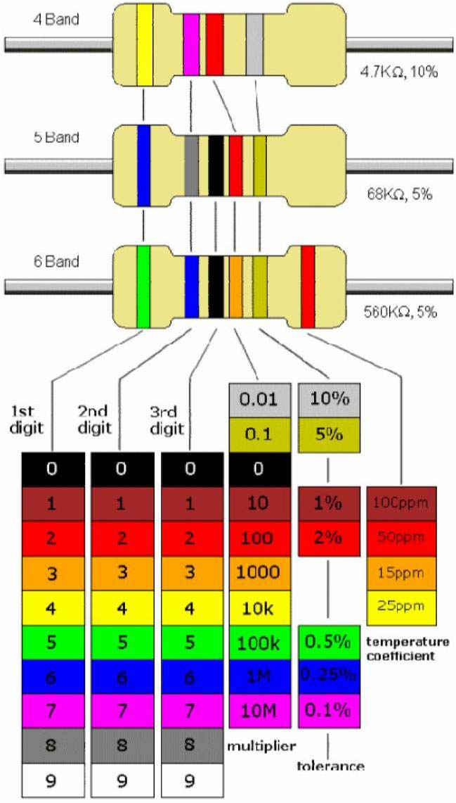
Resistor color code
The color code is read as follows:
1: Start with the band closest to one end of the resistor. The first band is the first digit of the resistance value.
2: The second band is the second digit of the resistance value.
3: The third band is the number of zeros following the second digit, or the multiplier.
4: The fourth band indicates the percent tolerance and is usually gold or silver.
For example, a 5% tolerance means that the actual resistance value is within ±5% of the color-coded value. Thus, a 100Ω resistor with a tolerance of ±5% can have an acceptable range of values from a minimum of 95Ω to a maximum of 105Ω.
Alphanumeric Labeling:-
Two or three digits,
and one of the letters R, K, or M are used to identify a resistance value.
The letter is used to indicate the multiplier, and its position is used to indicate decimal point position.
Thursday, 22 January 2015
Motherboard
A Chip:-
A chip (microchip) is an integrated circuit -a thin slice of silicon crystal packed with microscopic circuit elements.
Example: wires, transistors, capacitors, resistors.
A chip (microchip) is an integrated circuit -a thin slice of silicon crystal packed with microscopic circuit elements.
Example: wires, transistors, capacitors, resistors.
Manufacturing
Motherboard
Saturday, 27 December 2014
Steering Gear Box
Functions of Steering Gear Box:
1. It converts the Rotary movement of the steering wheel in to the angular turning of the front wheels.
2. It also multiplies drivers efforts and give MECHANICAL ADVANTAGE.
Types of Steering Gear Boxes:
1.Worm and Wheel Type
2. Re-circulating Ball Type
3. Rack and Pinion Type
4. Cam and Lever Type
5. Worm and Sector Type
1.Worm and Wheel Type: This type of steering gear has a square cut screw threads at the end of the steering column; which forms a worm, at the end of it a worm wheel is fitted and works rigidly with it. Generally covered shaft is used for the worm wheel. The worm wheel can be turned to a new position the drop arm can be readjusted to the correct working position.
2. Re-circulating Ball Type: In this type of gear box the endless chain of balls are provided between the worm and nut members. The nut form a ring of rack having an axial movement. So that the sector on the rocker shaft racks, the balls roll continuously between the worm and nut. Being provided with return chambers at the ends of the worm. This method reduces friction between worm and nut members. This type of steering gear is used for heavy vehicles.
3. Rack and Pinion Type: This is common manual type of steering gear box is used in most of the vehicles. In this type of steering a pinion is provided the bottom end of the steering column. The teeth of the pinion wheel in mesh with corresponding teeth provided on the rack, the end of which are connected to the stub axle through the rod. The rotating motion of the pinion operates the rack in FORE and AFT direction which in turn operates the stub axle.
4. Cam and Lever Type: The cam and lever steering uses one or two lever studs fitted in taper roller bearing. When the worm in the form of helical groove rotates the stub axle and it also rotates along with it. This imports a turning motion to the drop arm shaft.
5. Worm and Sector Type: In this type the worm on the end of the steering shaft meshes with a sector mounted on a sector shaft. When the worm is rotated by rotation of the steering wheel, the sector also turn rotating the sector shaft. Its motion is transmitted to the wheel through the linkage. The sector shaft is attached to the drop arm or pitmen arm.
Power Steering:
Power steering reduces much strain on the part of the driver while negotiating sharp curves. It makes easy to turn sharp corners. It is usually arranged to be operative when the effort of steering wheel exceeds a predetermined value. It is fitted on heavy commercial vehicles and medium cars.
1. It converts the Rotary movement of the steering wheel in to the angular turning of the front wheels.
2. It also multiplies drivers efforts and give MECHANICAL ADVANTAGE.
Types of Steering Gear Boxes:
1.Worm and Wheel Type
2. Re-circulating Ball Type
3. Rack and Pinion Type
4. Cam and Lever Type
5. Worm and Sector Type
1.Worm and Wheel Type: This type of steering gear has a square cut screw threads at the end of the steering column; which forms a worm, at the end of it a worm wheel is fitted and works rigidly with it. Generally covered shaft is used for the worm wheel. The worm wheel can be turned to a new position the drop arm can be readjusted to the correct working position.
2. Re-circulating Ball Type: In this type of gear box the endless chain of balls are provided between the worm and nut members. The nut form a ring of rack having an axial movement. So that the sector on the rocker shaft racks, the balls roll continuously between the worm and nut. Being provided with return chambers at the ends of the worm. This method reduces friction between worm and nut members. This type of steering gear is used for heavy vehicles.
3. Rack and Pinion Type: This is common manual type of steering gear box is used in most of the vehicles. In this type of steering a pinion is provided the bottom end of the steering column. The teeth of the pinion wheel in mesh with corresponding teeth provided on the rack, the end of which are connected to the stub axle through the rod. The rotating motion of the pinion operates the rack in FORE and AFT direction which in turn operates the stub axle.
4. Cam and Lever Type: The cam and lever steering uses one or two lever studs fitted in taper roller bearing. When the worm in the form of helical groove rotates the stub axle and it also rotates along with it. This imports a turning motion to the drop arm shaft.
5. Worm and Sector Type: In this type the worm on the end of the steering shaft meshes with a sector mounted on a sector shaft. When the worm is rotated by rotation of the steering wheel, the sector also turn rotating the sector shaft. Its motion is transmitted to the wheel through the linkage. The sector shaft is attached to the drop arm or pitmen arm.
Power Steering:
Power steering reduces much strain on the part of the driver while negotiating sharp curves. It makes easy to turn sharp corners. It is usually arranged to be operative when the effort of steering wheel exceeds a predetermined value. It is fitted on heavy commercial vehicles and medium cars.
Saturday, 13 December 2014
Steering System
STEERING SYSTEM
Introduction: This system provides the directional change in the movement of an Automobile and maintain in a position as per the driver’s decision without much strain on him.
REQUIREMENTS OF STEERING SYSTEM:
a. It must keep the wheel at all times in to rolling motion with out rubbing on the road.
b. This system should associate to control the speed.
c. It must light and stable.
d. It should also absorb the road shocks.
e. It must easily be operated with less maintenance.
f. It should have self-centering action to some extent.
Functions of Steering System:
1. It helps in swinging the wheels to the left or right.
2. It helps in turning the vehicle at the will of the driver.
3. It provides directional stability.
4. It is used to minimize the tyre wear and tear.
5. It helps in achieving self-centering efforts.
6. It absorbs major part of the road shocks.
Main Components of Steering System:
Following are the main components of steering system:
1. Steering Wheel
2. Steering column or shaft
3. Steering Gear
4. Drop Arm or Pitman Arm
5. Drag Link
6. Steering Arm
7. Track-Arms
8. Track Rod or Tie-Rod
9. Adjusting Screws
Monday, 1 December 2014
Electric Field
The potential of electric field of a point charge:-
If potential 0-level is chosen in infinity The electric field potential at a point in space is equal to the amount of work we done by electric force to move the test charge from the point in question to infinity, divided by charge. The electric potential created by a point charge Qsource, at a distance r from the charge (relative to the potential at infinity), can be shown to be:
Electric field:-
• Intensity of an electric field E (or strength of an electric field or electric field) is vector characteristic. It is defined as the ratio of the force F acting upon the test charge to the magnitude of the test charge.
• The electric field of a point charge can be obtained from Coulomb's law.
• The magnitude of electric field produced by point charge Qsource at a distance r from this charge (in a point of M is where the electric field is defined).
Field lines:-
• An electric field has both magnitude and direction. The distribution of an electric field in space is visually represented by the intensity lines (or lines of force or field lines). Electric field-lines are drawn according to the following rules:
The direction of the electric field is everywhere tangent to the field-lines, in the sense of the arrows on the lines. The magnitude of the field is proportional to the number of field-lines per unit area passing through a small surface normal to the lines.
• The lines of force of a potential electric field (electrostatic field) that is created by electric charges originate on positive charges and terminate on negative charges. The electric field is stronger where the field lines are close together than where they are farther apart.
Electric Dipole:-
• An electric dipole is a pair of point electric charges of equal magnitude but opposite sign, separated by some small distance.
• The distribution of the charge in a dipole can be characterized by a parameter called the dipole moment p. The dipole moment is a vector which is directed from the negative charge towards the positive charge and is defined as:
If potential 0-level is chosen in infinity The electric field potential at a point in space is equal to the amount of work we done by electric force to move the test charge from the point in question to infinity, divided by charge. The electric potential created by a point charge Qsource, at a distance r from the charge (relative to the potential at infinity), can be shown to be:
Electric field:-
• Intensity of an electric field E (or strength of an electric field or electric field) is vector characteristic. It is defined as the ratio of the force F acting upon the test charge to the magnitude of the test charge.
• The electric field of a point charge can be obtained from Coulomb's law.
• The magnitude of electric field produced by point charge Qsource at a distance r from this charge (in a point of M is where the electric field is defined).
Field lines:-
• An electric field has both magnitude and direction. The distribution of an electric field in space is visually represented by the intensity lines (or lines of force or field lines). Electric field-lines are drawn according to the following rules:
The direction of the electric field is everywhere tangent to the field-lines, in the sense of the arrows on the lines. The magnitude of the field is proportional to the number of field-lines per unit area passing through a small surface normal to the lines.
• The lines of force of a potential electric field (electrostatic field) that is created by electric charges originate on positive charges and terminate on negative charges. The electric field is stronger where the field lines are close together than where they are farther apart.
Electric Dipole:-
• An electric dipole is a pair of point electric charges of equal magnitude but opposite sign, separated by some small distance.
• The distribution of the charge in a dipole can be characterized by a parameter called the dipole moment p. The dipole moment is a vector which is directed from the negative charge towards the positive charge and is defined as:
Invoking Commands In AutoCAD
Invoking Commands In AutoCAD:-
When you start AutoCAD and you are in the drawing area, you need to invoke AutoCAD commands to perform any operation. AutoCAD has provided the following methods to invoke commands:
• Keyboard
• Menu
• Toolbar
• Shortcut menu
• TOOL PALETTES
• Keyboard:-
You can invoke any AutoCAD command at the keyboard by typing the command name at the Command prompt, and then pressing ENTER or the SPACEBAR. If the Command prompt is not displayed as the last line in the command window area, you must cancel the existing command by pressing Esc (escape) on the keyboard. The following example shows how to invoke the LINE command from the keyboard:
Command: LINE or L « (L is command alias)
• Menu:-
You can also select commands from the menu. The menu bar that displays the menu bar titles is at the top of the screen. As you move the cursor over the menu bar, different titles are highlighted. You can choose the desired item by pressing the pick button of your pointing device. Once the item is selected, the corresponding menu is displayed directly under the title. Some of the menu items in the menu display an arrow on the right side, which indicates that the menu item has a cascading menu. You can display the cascading menu by moving the arrow pointer over the item and press the pick button.
• Toolbar:-
In Windows, the toolbar is an easy and convenient way to invoke a command. For example, you can invoke the LINE command by choosing the Line button in the Draw toolbar. When you choose a command from the toolbar, the command prompts are displayed in the command window.
Toolbar has numerous features that help to control their appearance. Toolbar features include:
1: Displaying Toolbars: The various toolbars can be displayed by selecting their respective check boxes in the Toolbars tab of the Customize dialog box. The Customize dialog box can be invoked by selecting Toolbars in the View menu. You can also display a toolbar from the shortcut menu by selecting the name of the toolbar. The shortcut menu can be displayed by right clicking anywhere on any toolbar on the screen.
2: Moving and Reshaping Toolbars
• Shortcut Menu:-
AutoCAD has provided shortcut menus as an easy and convenient way of invoking commands. These menus are context sensitive. They are invoked by right-clicking and displayed at the cursor location.
You can also right-click on the command window to display the shortcut menu. This menu displays the six most recently used commands and some of the window options like Copy and Paste.
You can right-click on the status bar to display the shortcut menu. This menu contains the options to change the settings of drawing tools.
• TOOL PALETTES:-
AutoCAD has provided TOOL PALETTES as an easy and convenient way of placing and sharing hatch patterns and blocks in the current drawing. By default, AutoCAD displays the Tool Palettes as a window on the right of the drawing area. Also, the TOOL PALETTES window can be turned on or off by either choosing the Tool Palettes button available on the Standard toolbar or by pressing the CTRL and 3 keys.
Sunday, 30 November 2014
Format Specifiers and Escape Sequences
Format Strings and Escape Sequences:-
All format specifiers start with a percent sign (%) and are followed by a single letter indicating the type of data and how data are to be formatted.
List of commonly used format specifiers:
%c – used for single char in C
scanf(“%c”, &ch);
printf(“%c”, ch);
%d – decimal number (whole number)
scanf(“%d”, &num);
printf(“%d”, num);
%e – scientific notation/exponential form
scanf(“%e”, &result);
printf(“%e”, result);
%f – number with floating or decimal point
scanf(“%f”, &pesos);
printf(“%f”, pesos);
%u – unsigned number
scanf(“%u”, &nos);
printf(“%u”, nos);
%x – hexadecimal number
scanf(“%x”, &value);
printf(“%x”, value);
%X – capital number for hexadecimal number
scanf(“%X”, &nos);
printf(“%X”, nos);
%o – octal number
scanf(“%o”, &value);
printf(“%o”, value);
%s – string of characters
scanf(“%s”, str);
printf(“%s”, str);
%% - print a percent sign
scanf(“%%”, &value);
printf(“%%”, value);
List of commonly used escape sequences:
\\ - prints backslash
\’ - prints single quotes
\” - prints double quotes
\? - prints question mark
\n - newline
Associativity of Operators:
i = 2 * 3 / 4 + 4 / 4 + 8 - 2 + 5 / 8
i = 6 / 4 + 4 / 4 + 8 - 2 + 5 / 8 operation: *
i = 1 + 4 / 4 + 8 - 2 + 5 / 8 operation: /
i = 1 + 1+ 8 - 2 + 5 / 8 operation: /
i = 1 + 1 + 8 - 2 + 0 operation: /
i = 2 + 8 - 2 + 0 operation: +
i = 10 - 2 + 0 operation: +
i = 8 + 0 operation : -
i = 8 operation: +
_______________________________________________________________________
kk = 3 / 2 * 4 + 3 / 8 + 3
kk = 1 * 4 + 3 / 8 + 3 operation: /
kk = 4 + 3 / 8 + 3 operation: *
kk = 4 + 0 + 3 operation: /
kk = 4 + 3 operation: +
kk = 7 operation: +
________________________________________________________________________
Writing a Program
Writing Program:-
In order to write program in any programming language, it is necessary to know what about its command and syntax. Programmer must also know that what are the basic usage of commands and other programming structure. Programs written in C language is really not much difficult to understand that one written in any other language, once you become used to the basic syntax.
Function Definition: All C programs are divided into units called ‘functions’.
Every C program consists of one or more functions. Consider the following program:
#include <stdio.h>
void main(void)
{
printf ( "Hello, World");
}
The above program has only one function “main”. This function is one to which control is passed from the operating system when the program is run, i.e. it is the first function executed. The word “void” preceding “main” specifies that the function “main” will not return a value. The second “void” in paranthesis specifies that the function takes no arguments.
Input Statement:-
A statement used to input a single character or a sequence of characters from the keyboard.
1. getch – a function used to input a single character from the keyboard without echoing the character on the monitor.
Syntax: getch( );
Example: ch = getch( );
2. getche – a function used to input a single character from the keyboard, the character pressed echoed on the monitor.
Syntax: getche( );
Example: ch = getche( );
3. getchar – a function used to input a single character from the keyboard, the character pressed echoed on the monitor, terminated by pressing ENTER key.
Syntax: getchar( );
Example: ch = getchar( );
4. gets – a function used to input sequence of character from the keyboard, spaces are accepted, terminated by pressing enter key.
Syntax: gets( );
Example: gets(ch);
5. scanf – a function used to input single character or sequence of characters from the keyboard, it needs the control string codes in able to recognized. Spaces are not accepted upon inputting. Terminated by pressing spacebar.
Syntax: scanf(“control string codes”, identifier);
Example: scanf(“%d”, &num);
Output Statement:-
A statement used to display the argument list or string on the monitor.
1. printf – a function used to display the argument list on the monitor. It sometimes needs the control string codes to help display the remaining argument on the screen.
Syntax: printf(“control string codes”, argument list);
Example: printf(“Hello, %s, you are %d years old”, name, age);
2. putchar – a function used to display the argument list or string on the monitor. It is like overwriting a character.
Syntax: putchar( );
Example: putchar(tolower (ch));
3. puts – a function used to display the argument list or string on the monitor. It does not need the help of the control string codes.
Syntax: puts( );
Example: puts(“hello”);
Friday, 14 November 2014
Wednesday, 12 November 2014
Electrostatics
Electrostatics:-
• Electrostatics is the study of electric charge at rest.
(Or more or less at rest, in contrast with current electricity.)
Electrical Charges:-
• Electric charge is a fundamental property of matter.
Two types of electric charges:
• Positive charge - every proton has a single positive charge.
• Negative charge - every electron has a single negative charge.
• An object with an excess of electrons is negatively charged.
• An object with too few electrons (too many protons) is positively charged.
• An object with the same number of electrons and protons is neutral.
• Like charges repel.
• Opposite charges attract.
Elementary Charges:-
• Protons carry the smallest positive charge.
• Protons and uncharged neutrons generally reside in an atom’s nucleus.
• Protons are held in the nucleus by the strong force.
• The smallest negative charge is the charge on the electron.
• In normal atoms, electrons orbit the nucleus.
• The electric force between electrons and protons supplies the centripetal force to keep electrons in the atom.
• The charges carried by the proton and electron are equal in size.
• The mass of the proton is about 2000 times the mass of the electron.
Units of Charge:-
• The SI unit of charge is the Coulomb.
1 Coulomb = the charge of (6.24 x 10^18) electrons.
e = (1.602 x 10^-19) C
Charge is Conserved:-
• Electric charge is conserved:
– Electric charge moves from one place to another: (no case of the net creation or destruction of electric charge has ever been observed.)
• In solids, only electrons can move.
• In liquids, gasses, and plasma, both positive and negative ions are free to move.
Sunday, 2 November 2014
Integrated Development Environment (IDE)
Integrated Development Environment:-
An integrated development environment (IDE), also known as integrated design environment and integrated debugging environment, is a type of computer software that assists computer programmers in developing software.
IDEs normally consist of a source code editor, a compiler and/or interpreter, build-automation tools, and (usually) a debugger.
Source code editor: It is a text editor program designed specifically for editing source code of computer programs by programmers. Source code editors may have features specifically designed to simplify and speed up input of source code, such as syntax highlighting and auto complete.
Compiler: It is a computer program (or set of programs) that translates text written in a computer language (the source language) into another computer language (the target language).
Interpreter: It is a computer program that executes, or performs, instructions written in a computer programming language.
Debugger: It is a computer program that is used to test and debug other programs.
Saturday, 18 October 2014
Introduction to AutoCAD 2004
Learning Objectives:-
1: Start AutoCAD and start a drawing in AutoCAD.
2: Understand the various components of the initial AutoCAD screen.
3: Invoke AutoCAD commands from the keyboard,menu,toolbar,shortcut menu,screen menu, and digitizer.
4: Understand the functioning of dialog boxes in AutoCAD.
5: Start a new drawing using the QNEW command and the Startup dialog box.
6: Save the work using various file-saving commands.
7: Close a drawing.
8: Open an existing drawing.
9: Understand the concept of Multiple Document Environment.
10: Quit AutoCAD.
11: Use the various options of AutoCAD’s help.
12: Understand the use of Active Assistance, Learning Assistance, and other interactive help topics.
AutoCAD SCREEN COMPONENT:-
The various components of the initial AutoCAD screen are:
• Drawing Area
• Command Window
• Status Bar
• Status Bar Tray Options
• Drawing Area:-
The drawing area covers the major portion of the screen. Here you can draw the various objects and use the various commands. There is a coordinate system icon at the lower left corner of the drawing area. The window also has the standard Windows buttons such as close, minimize, scroll bar, and so on, that have the same functions as for any other standard window.
• Command Window:-
The command window is present at the bottom of the drawing area and has the Command prompt where you can enter the commands. You can change the size of the window by placing the cursor on the top edge and then dragging it. By default the command window displays only three lines.
• Status Bar:-
The status bar is displayed at the bottom of the screen. This bar contains some useful information and buttons that will make it easy to change the status of some AutoCAD functions. To change the status, you must choose the buttons that toggle between on and off.
The various options under the Status Bar are:
• Coordinate display
• Snap
• Grid
• Ortho
• Polar
• Osnap
• Otrack
• LWT
• Model
• Coordinate display:-
The Coordinates information is displayed in the left corner of the status bar. You can select this coordinate button to toggle between on and off. The COORDS system variable controls the type of display of the coordinates.
• Snap:-
If Snap Mode is on, the Snap button is displayed as pressed in the status bar; otherwise, it is not displayed. This allows you to move the cursor in fixed increments. You can also use the function key F9 as a toggle key to turn Snap off or on.
• Grid:-
If Grid Display is on, grid lines are displayed on the screen. These lines are used as reference lines in a drawing. The function key F7 can be used to turn the grid display on or off.
• Ortho:-
The Ortho Mode allows you to draw lines at right angles only. If this mode is on, the ORTHO button is pressed in the status bar. You can use the F8 key to turn Ortho on or off.
• Polar:-
If you turn the Polar Tracking on, the movement of the cursor is restricted along a path based on the angle set as the polar angle settings. Choosing the POLAR button in the status bar turns the Polar Tracking on. You can also use the function key, F10.
• Osnap:-
When Object Snap is on, you can use the running object snaps to snap on to a point. If Object Snap is on, the OSNAP button is displayed as pressed in the status bar. You can also use the F3 key to turn the Object Snap on or off.
• Otrack:-
Choosing the OTRACK button, turns Object Snap Tracking on or off.
• LWT:-
Choosing this button in the status bar, allows you to turn on or off the display of lineweights in the drawing. If the LWT button is not pressed, the display of Lineweight is turned off.
• Model:-
The Model button is displayed in the status bar when you are working in the model space to create drawings. You can choose this button to shift to the layouts (paper space) where you can create drawing views. Once you switch to layouts, this button is replaced by the PAPER button. You can choose the PAPER button to shift back to the model space.
Tuesday, 30 September 2014
Types of Chassis frame
TYPES OF CHASSIS FRAMES:-
There are three types of frames:
1. Conventional frame
2. Integral frame
3. Semi-integral frame
1. Conventional frame: It has two long side members and 5 to 6 cross members joined together with the help of rivets and bolts. The frame sections are used generally.
a. Channel Section - Good resistance to bending
b. Tabular Section - Good resistance to Torsion
c. Box Section - Good resistance to both bending and Torsion
2. Integral Frame: This frame is used now a days in most of the cars. There is no frame and all the assembly units are attached to the body. All the functions of the frame carried out by the body itself. Due to elimination of long frame it is cheaper and due to less weight most economical also. Only disadvantage is repairing is difficult.
3. Semi - Integral Frame: In some vehicles half frame is fixed in the front end on which engine gear box and front suspension is mounted. It has the advantage when the vehicle is met with accident the front frame can be taken easily to replace the damaged chassis frame. This type of frame is used in FIAT cars and some of the European and American cars.
VARIOUS LOADS ACTING ON THE FRAME:-
Various loads acting on the frame are:
1. Short duration Load - While crossing a broken patch.
2. Momentary duration Load - While taking a curve.
3. Impact Loads - Due to the collision of the vehicle.
4. Inertia Load - While applying brakes.
5. Static Loads - Loads due to chassis parts.
6. Over Loads - Beyond Design capacity.
STATE THE DIFFERENT BODIES USED IN AUTOMOBILES:-
The Automobile bodies are divided in two groups:
A: Passenger body
B: Commercial body
According to Chassis design the body can divided into:
1. Conventional Type
2. Integral Type
3. Semi- Integral Type
According to other usage:
1. Light vehicle Bodies - cars, jeeps
2. Heavy vehicle Bodies - busses, lorries
3. Medium vehicle Bodies - vans, metadoors
REQUIREMENTS OF BODIES FOR VARIOUS TYPES OF VEHICLE:-
The body of the most vehicle should fulfill the following requirements:
1. The body should be light.
2. It should have minimum number of components.
3. It should provide sufficient space for passengers and luggage.
4. It should withstand vibrations while in motion.
5. It should offer minimum resistance to air.
6. It should be cheap and easy in manufacturing.
7. It should be attractive in shape and colour.
8. It should have uniformly distributed load.
9. It should have long fatigue life.
10.It should provide good vision and ventilation.
Basic structure of Vehicle
Chassis frame & its functions:
Introduction of Chassis Frame: Chassis is a French term and was initially used to denote the frame parts or Basic Structure of the vehicle. It is the back bone of the vehicle. A vehicle with out body is called Chassis. The components of the vehicle like Power plant, Transmission System, Axles, Wheels and Tyres, Suspension, Controlling Systems like Braking, Steering etc., and also electrical system parts are mounted on the Chassis frame. It is the main mounting for all the components including the body. So it is also called as Carrying Unit.
The following main components of the Chassis are:
1. Frame: it is made up of long two members called side members riveted together with the help of number of cross members.
2. Engine or Power plant: It provides the source of power.
3. Clutch: It connects and disconnects the power from the engine fly wheel to the transmission system.
4. Gear Box
5. U Joint
6. Propeller Shaft
7. Differential
FUNCTIONS OF THE CHASSIS FRAME:-
2. To support the load of the body, engine, gear box etc.
3. To withstand the forces caused due to the sudden braking or acceleration.
4. To withstand the stresses caused due to the bad road condition.
5. To withstand centrifugal force while cornering.
Subscribe to:
Posts (Atom)


.png)
.png)