Thursday, 30 July 2015

Electric Circuit

The Electric Circuit:-
                                A basic electric circuit is an arrangement of physical components that use voltage, current and resistance to perform some useful function.

Direction of Current:-
               –Two conventions for the direction of electric current.
                               •Electron flow direction:
–Preferred by many in the field of electrical and electronics technology, current is out of negative terminal of voltage source, through the circuit, and into the positive terminal of the source.  
•Conventional current direction:
–Current is out of positive terminal of voltage source through the circuit into the negative terminal of the source.


Digital Multimeter:

Sunday, 1 February 2015

Engineering Design Process


Engineering Design Process
The Engineering Design Process is a series of steps that lead the engineer to develop a new product or system, or to solve engineering problems. As it is a cyclical process, so that the engineers repeat the steps as many times as needed, making improvements along the way.


An engineer, either he is a trainee engineer or chief engineer, he must follow this process to achieve his goal. The steps of this process are as follows:
1) ASK: Identify the problem, identify the need, criteria and constraints.
2) IMAGINE: Develop possible solutions. Brainstorm ideas, choose the best one.
3) PLAN: Build a model or prototype, Make a list of materials you will need.
4) CREATE: Follow your plan and create something, Test and evaluate prototype.
5) IMPROVE: Redesign as needed, modify your design to make it better.


Two key themes of the engineering design process are teamwork and design. Encourage students to follow the steps of the design process to strengthen their understanding of open-ended design and emphasize creativity and practicality. 

Tuesday, 27 January 2015

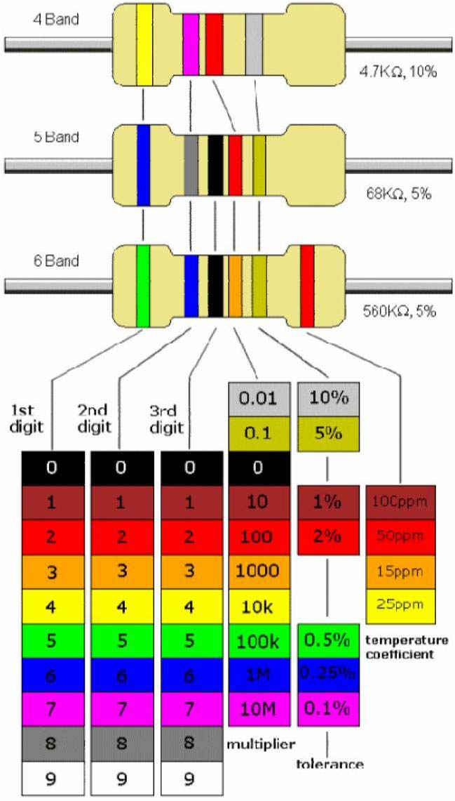
Resistor color code


The color code is read as follows:
1: Start with the band closest to one end of the resistor. The first band is the first digit of the resistance value.
2: The second band is the second digit of the resistance value.
3: The third band is the number of zeros following the second digit, or the multiplier.
4: The fourth band indicates the percent tolerance and is usually gold or silver.


For example, a 5% tolerance means that the actual resistance value is within ±5% of the color-coded value. Thus, a 100Ω resistor with a tolerance of ±5% can have an acceptable range of values from a minimum of 95Ω to a maximum of 105Ω.


Alphanumeric Labeling:-
Two or three digits, and one of the letters R, K, or M are used to identify a resistance value.
The letter is used to indicate the multiplier, and its position is used to indicate decimal point position.


Thursday, 22 January 2015

Motherboard

A Chip:-
A chip (microchip) is an integrated circuit -a thin slice of silicon crystal packed with microscopic circuit elements.
Example: wires, transistors, capacitors, resistors.


Manufacturing

Motherboard